3.2. nwdiagの一例#

nwdiagのコンセプトは、PlantUMLに移植されています。オリジナルのnwdiagとPlantUMLのnwdiagを比べてみます。

PlantUMLでのnwdiag図の構文はオリジナルのnwdiagのそれをそのまま採用しているようで、オリジナルのnwdiagの 例をPlantUMLを実行することができました(結果は少しことなりますが)。
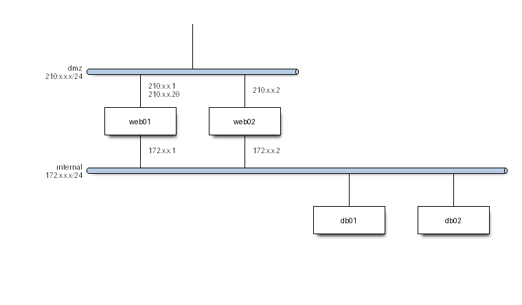
図 3.20 オリジナルのnwdiagでの処理結果#

nwdiag {
   network dmz {
   address = "210.x.x.x/24"

   // set multiple addresses (using comma)
   web01 [address = "210.x.x.1, 210.x.x.20"];
   web02 [address = "210.x.x.2"];
   }
   network internal {
   address = "172.x.x.x/24";

   web01 [address = "172.x.x.1"];
   web02 [address = "172.x.x.2"];
   db01;
   db02;
   }
}

図 3.21 http://blockdiag.com/ja/nwdiag/nwdiag-examples.html からの例をPlantUMLで処理#

<style>
nwdiagDiagram {
  network {
    BackGroundColor green
    LineColor red
    LineThickness 1.0
    FontSize 18
    FontColor navy
  }
  server {
    BackGroundColor pink
    LineColor yellow
    LineThickness 1.0
    ' FontXXX only for description or label
    FontSize 18
    FontColor #blue
  }
  arrow {
    ' FontXXX only for address
    FontSize 17
    FontColor #red
    FontName Monospaced
    LineColor black
  }
  group {
    BackGroundColor cadetblue
    LineColor black
    LineThickness 2.0
    FontSize 11
    FontStyle bold
    Margin 5
    Padding 5
  }
}
</style>
nwdiag {
  network DMZ {
      address = "y.x.x.x/24"
      web01 [address = "y.x.x.1"];
      web02 [address = "y.x.x.2"];
  }

   network Internal {
    web01;
    web02;
    db01 [address = "w.w.w.z", shape = database];
  }

    group {
    description = "long group label";
    web01;
    web02;
    db01;
  }
}

図 3.22 https://plantuml.com/ja/nwdiag から#

図の色などの指定は、PlantUMLの形式を使います。

nwdiag {
  inet [shape = cloud];
  inet -- router;

  // define group at outside network definitions
  group {
    color = "#FF7777";

    web01;
    web02;
    db01;
  }

  network dmz {
   address = "y.x.x.h/24"
    router[address = "y.x.x.254"];
    web01 [address = "y.x.x.1"];
    web02 [address = "y.x.x.2"];

  }
  network internal {
    web01;
    web02;
    db01;
  }
}

図 3.23 http://blockdiag.com/ja/nwdiag/nwdiag-examples.html から PlantUMLで処理色指定なども有効になっています。#

@startuml
!include <office/Servers/application_server>
!include <office/Servers/database_server>

nwdiag {
network dmz {
address = "210.x.x.x/24"

   ' set multiple addresses (using comma)
   web01 [address = "210.x.x.1, 210.x.x.20",  description = "<$application_server>\n web01"]
   web02 [address = "210.x.x.2",  description = "<$application_server>\n web02"];
}
network internal {
   address = "172.x.x.x/24";

   web01 [address = "172.x.x.1"];
   web02 [address = "172.x.x.2"];
   db01 [address = "172.x.x.100",  description = "<$database_server>\n db01"];
   db02 [address = "172.x.x.101",  description = "<$database_server>\n db02"];
   }
}
@enduml

図 3.24 スプライト(アイコン)の使用例#

3.2.1. rackdiagおよびpacketdiag#

さすがにplantUML 内ではrackdiagやpacketdiag は動作しない様です。以下は blockdiag/nwdiagの配布に含まれる、 rackdaigおよびpacketdiagで作成した図です。

リスト 3.13 rackdiag の入力例#
rackdiag {
// Change order of rack-number as ascending
ascending;

// define height of rack
12U;

// define description of rack
description = "Tokyo/1234 East";

// define rack units
1: UPS [2U];   // define height of unit
3: DB Server [5kg]  // define weight of unit
4: Web Server [0.5A]  // define ampere of unit
5: Web Server
6: Web Server
7: Load Balancer
8: L3 Switch
}
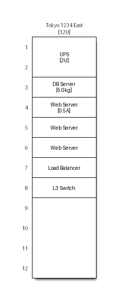
図 3.25 rackdiagディレクティブでの作図例#
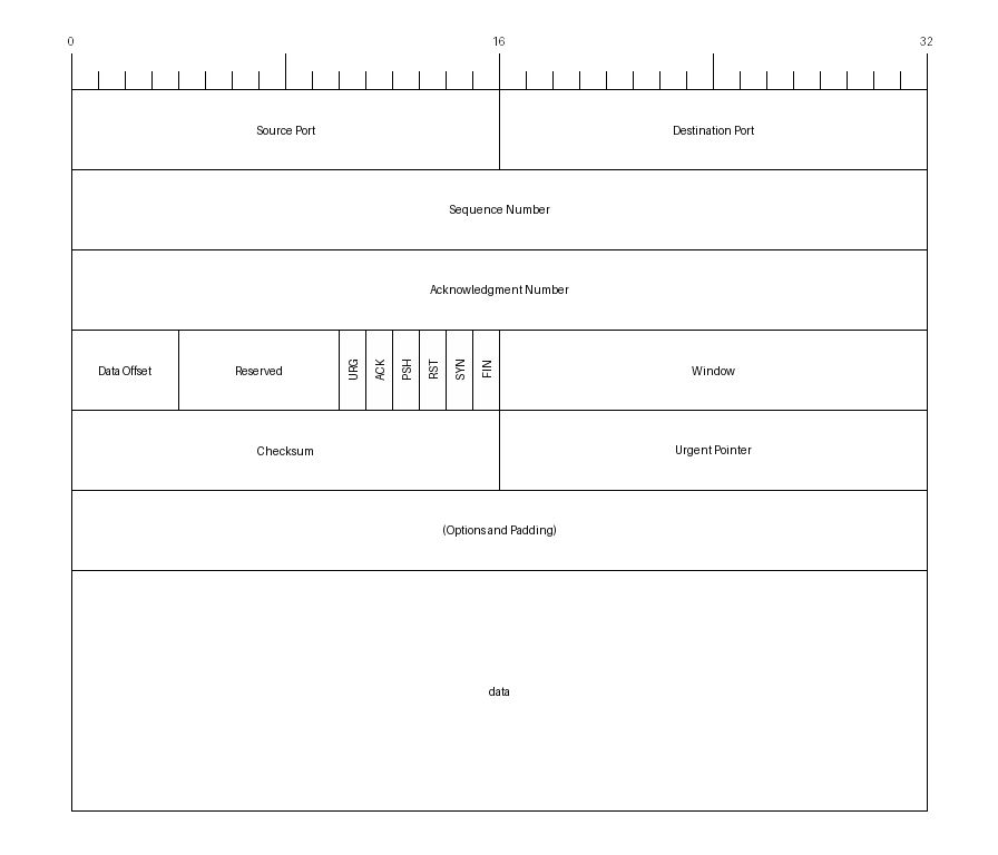
図 3.26 packdiagディレクティブでの作図例#

3.2.2. J-PARC制御のネットワーク#

  •      nwdiag {
          network WAN{
          address = "x.x.x.x/32"
          }
          network JLAN-DMZ{
          address = "x.x.x.x/32"
          }
        network J-LAN-local {
        address = "210.x.x.x/24"

        // set multiple addresses (using comma)
        web01 [address = "210.x.x.1, 210.x.x.20"];
        web02 [address = "210.x.x.2"];
        }
        network cont-dmz {
        address = "210.x.x.x/24"

        // set multiple addresses (using comma)
        web01 [address = "210.x.x.1, 210.x.x.20"];
        web02 [address = "210.x.x.2"];
        }

        network cont-CTR{

        }
        network cont-MR {
        address = "172.x.x.x/24";

        web01 [address = "172.x.x.1"];
        web02 [address = "172.x.x.2"];
        db01;
        db02;
        }
     }

    図 3.27 J-PARC制御ネットワークの構成図#